 smabo
smaboRoadmap#
This page is the guide for the 'smabo-esp32' node on the roadmap below.
This guide assumes you have completed the Base Parts guide.
Overview#
This page explains how to set up smabo-esp32.
smabo-esp32 is responsible for:
- Controlling sensors and actuators connected to the ESP32
Required Parts#
The following parts are required to implement this feature.
| Part | Product URL | Notes |
|---|---|---|
| ESP32-DevKitC | link | Compatible alternatives OK |
| Breadboard (SAD101) |
link | Standard breadboards have 5 holes per row, but this one has 6 — required for the ESP32's width. |
| Jump wires | link | - |
| Battery box (AA ×4, battery-snap compatible) | link | Battery snap version is recommended for easier handling. |
| Battery snap (for battery box) | link | A version with connector pins is recommended — easier to insert into the breadboard and less likely to come loose. |
| Rechargeable AA batteries × 4 | link | Rechargeable batteries are recommended. |
| Battery charger | link | - |
| Servo motor driver PCA9685 | link | Compatible alternatives OK, but only needed if implementing Hand / Neck / Robot Arm features. |
| Mini breadboard | link | Choose one with an adhesive backing. |
| TB6612FNG dual motor driver | link | Compatible alternatives OK (though a version without pre-soldered pin headers will require soldering yourself). Only needed if implementing Mobile Robot / Encoder Mobile Robot features. |
Setting Up smabo-esp32#
Installing Thonny (Flash Tool)#
Download and install Thonny for your OS from:
Once installation is complete, launch Thonny.
Flashing the Source Code
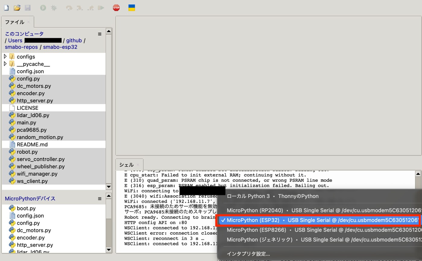
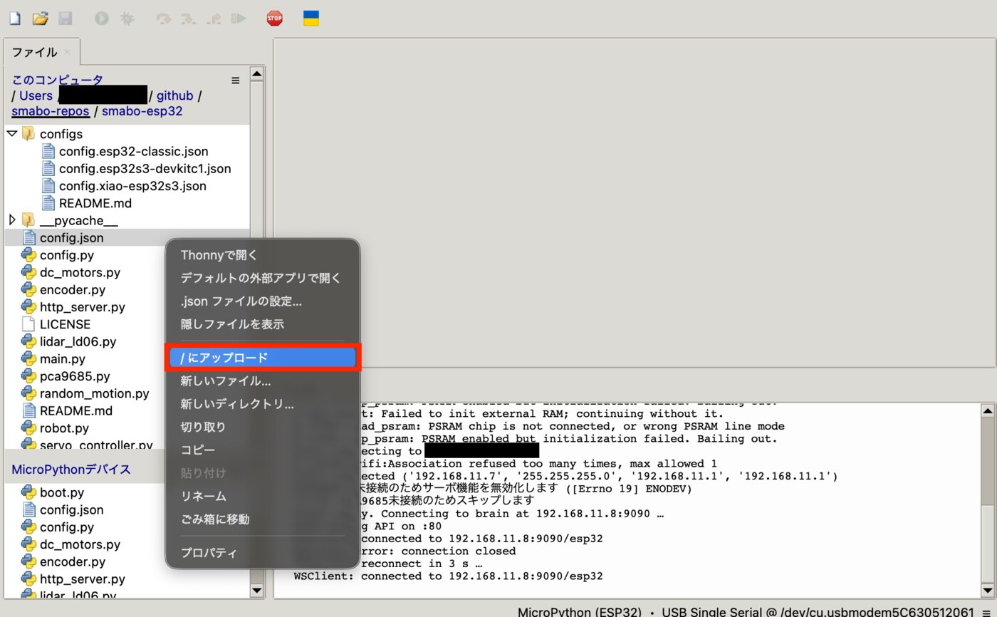
Connect the ESP32 to your PC via USB, then click the bottom-right button and select 'MicroPython (ESP32)'.
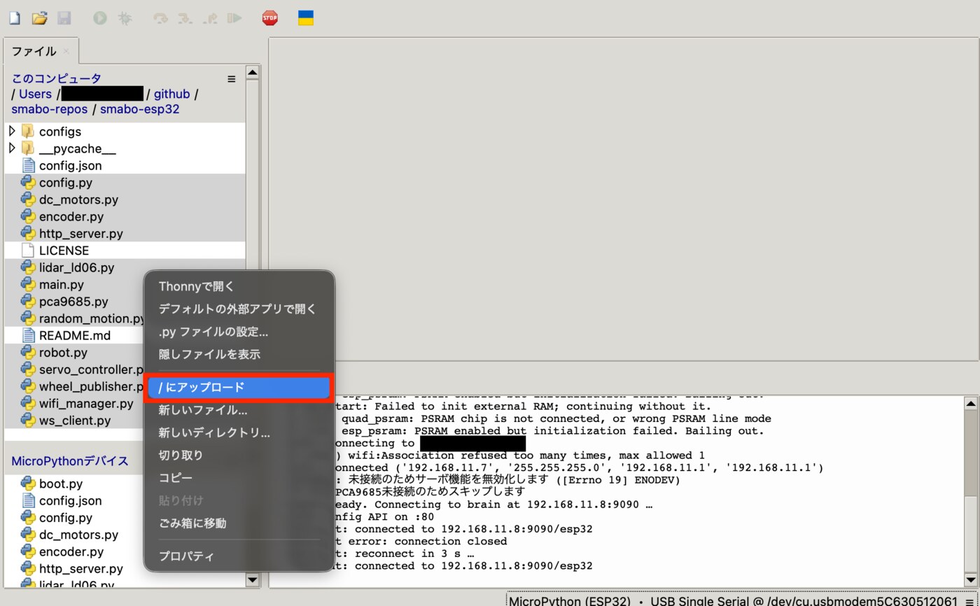
Select all Python files inside 'smabo-esp32', right-click and choose 'Upload to /' to flash them to the ESP32.
Flashing the Config File
Next, flash the config file.
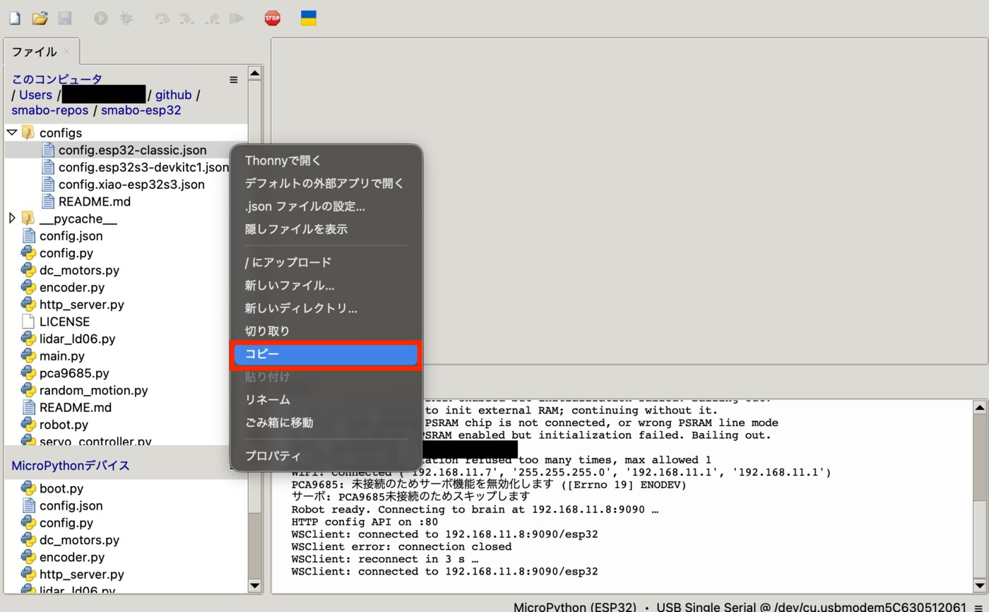
From the config directory, select the JSON file matching your ESP32 model and copy it as 'config.json'.
Fill in the following fields for your environment:
wifi/ssid— SSID of the network to connect towifi/password— password of that network
WiFi frequency note
ESP32 only supports 2.4 GHz WiFi.
- SSIDs ending in 'G' (e.g., Buffalo-G-xxxx) are 2.4 GHz
- SSIDs ending in 'A' (e.g., Buffalo-A-xxxx) are 5 GHz
Use the 'G' SSID here.
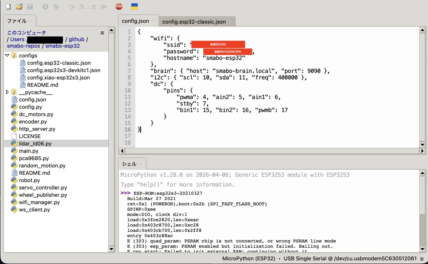
Once you have filled in the settings, flash config.json to the ESP32 the same way you flashed the source code.
3D Printing Parts#
Print the newly added parts on your 3D printer.
Because slicer software varies by printer model, only key points are noted here rather than step-by-step slicer instructions.
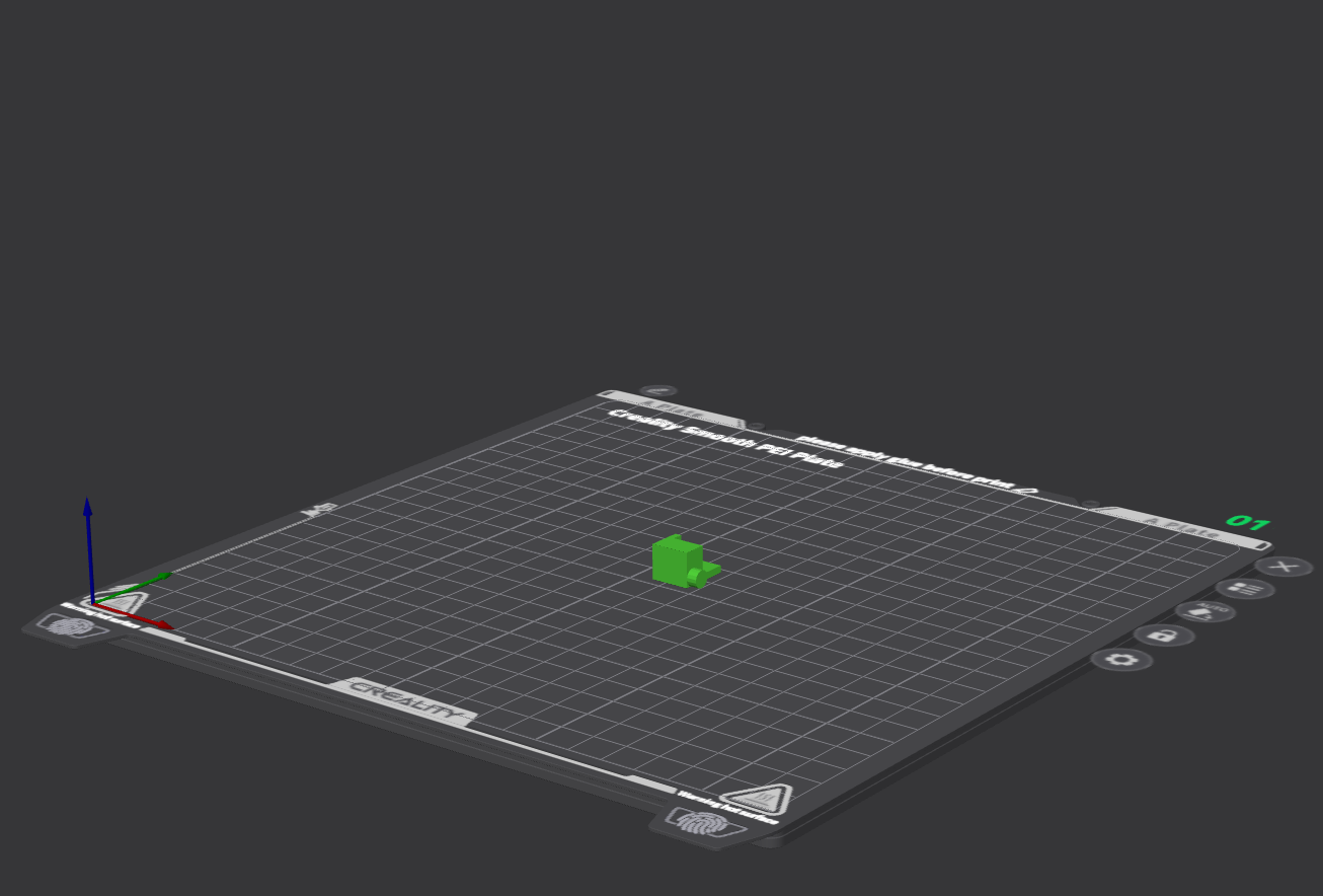
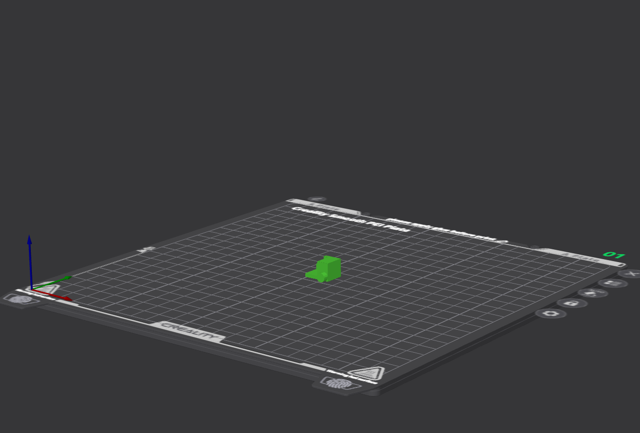
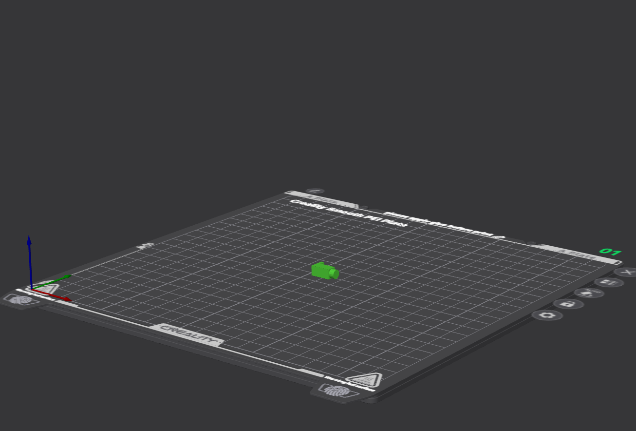
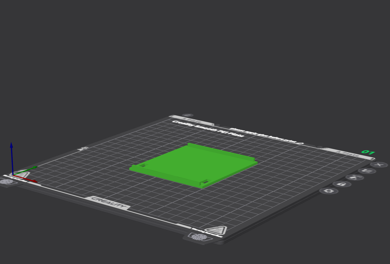
Print the following parts oriented as shown in the images.
Printing tips
- Orient the convex parts sideways to prevent breakage at the base when attaching/detaching.
- Always enable support material.
- smabo-hardware/stl/base/bread_board_stopper_bottom_l.stl
- smabo-hardware/stl/base/bread_board_stopper_bottom_r.stl
- smabo-hardware/stl/base/bread_board_stopper.stl
- smabo-hardware/stl/base/mini_bread_boad_stand.stl
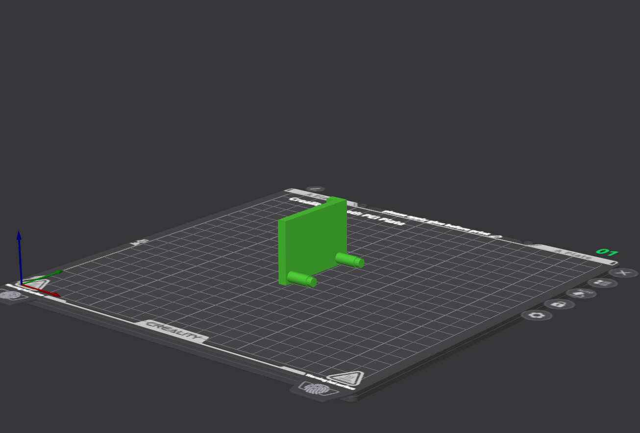
- smabo-hardware/stl/base/pca9685_stopper_l.stl
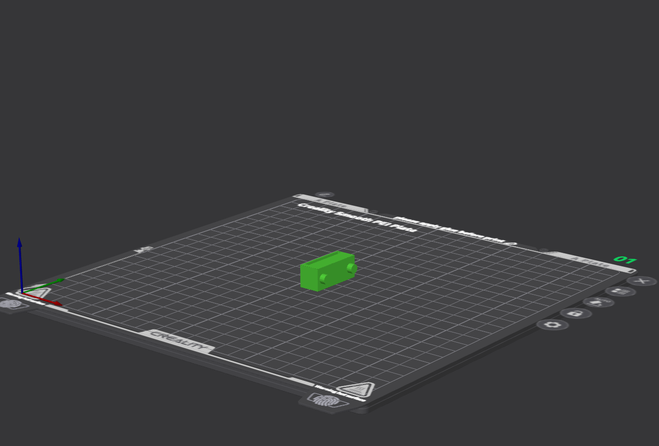
- smabo-hardware/stl/base/pca9685_stopper_r_bottom.stl
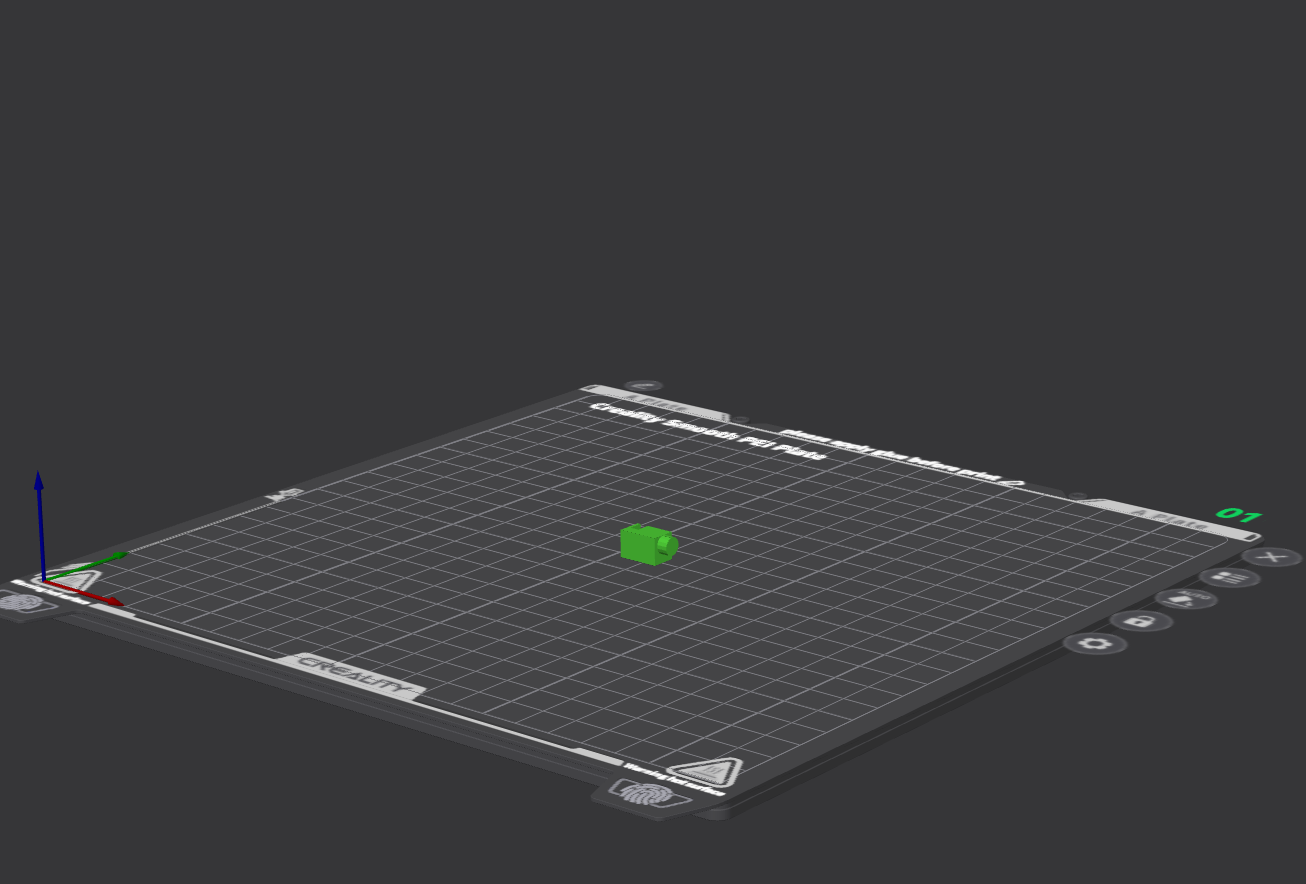
- smabo-hardware/stl/base/pca9685_stopper_r_top.stl
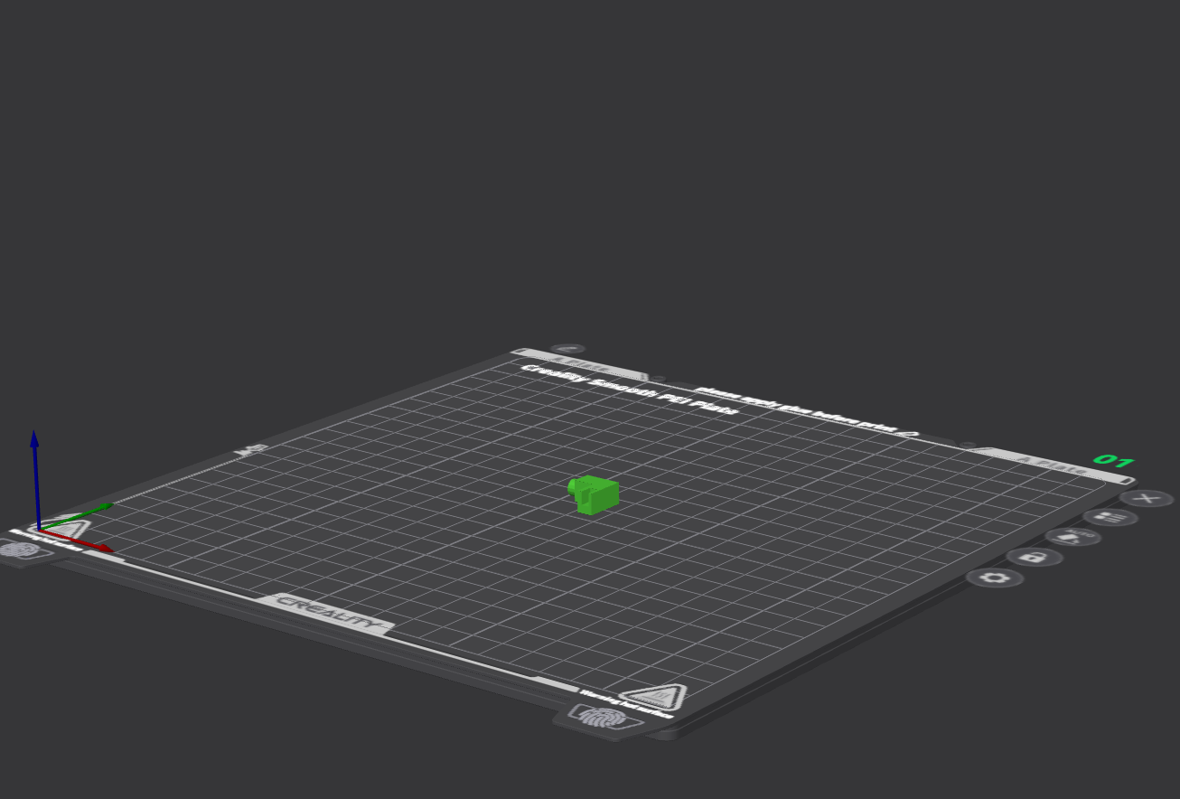
- [Optional] smabo-hardware/stl/base/in_base_plate_wire_hole.stl
- This part can be used as an internal divider inside smabo.
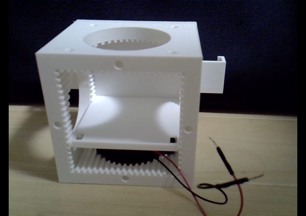
- This part can be used as an internal divider inside smabo.
About the Breadboard#
The SAD101 ships with a jumper wire inserted in the middle of the + rail.
In smabo, the + rail is split into two zones:
- Right side of + rail → 6 V (battery box)
- Left side of + rail → 5 V (ESP32 output)
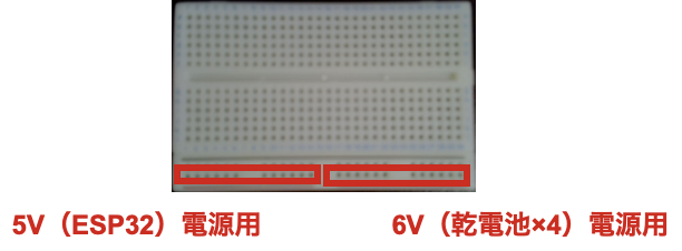
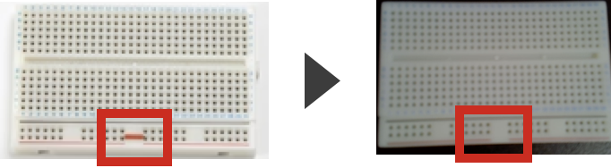
Therefore, remove the factory-installed jumper wire in the center of the + rail.
Inside the breadboard
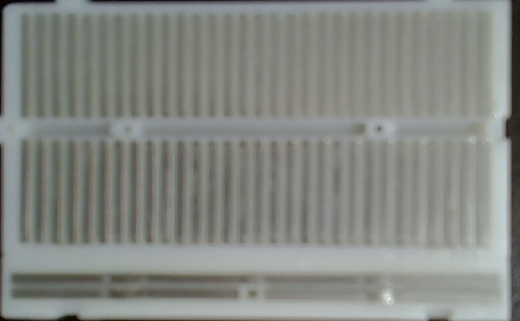
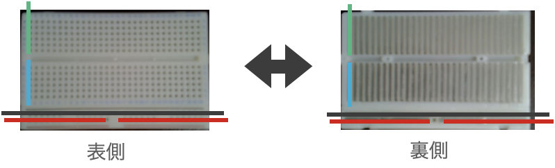
Looking at the back of the breadboard, you can see metal strips running along each row.
Any holes connected to the same strip are electrically connected, so multiple jump wires inserted in those holes form a circuit.
On the SAD101 in particular, the + rail is split in the middle — left and right are separate. The factory jumper wire was there to bridge them into one continuous rail.
Because we use different voltages on each side, that jumper must be removed.
Assembly#
Assemble the required parts as shown in the video below.
Note: the video also includes parts printed in previous steps.
Assembly tips
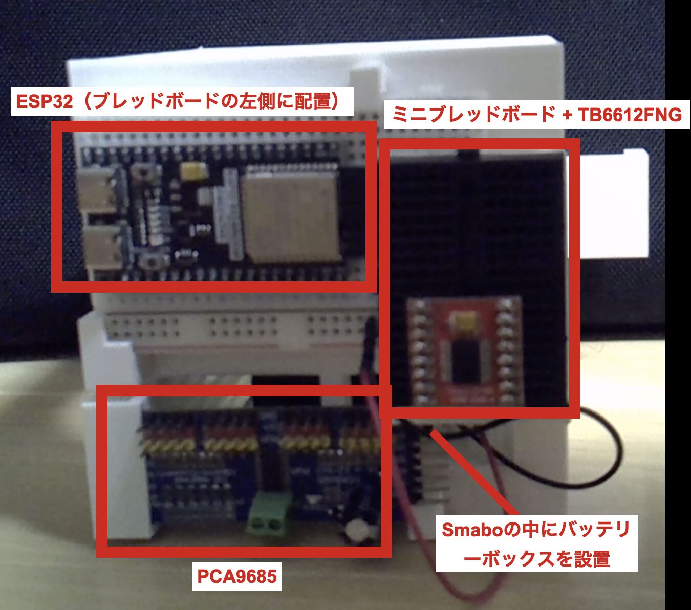
Use the printed parts to mount the breadboard, PCA9685, and mini breadboard. Pay particular attention to the following:
- Insert the ESP32 into the left end of the breadboard.
- Attach the mini breadboard using its adhesive backing.
- Place the battery box inside smabo and route only the jump wires outside, connecting them to the breadboard.
- Wiring positions are explained in the Wiring section below.
Wiring#
About the breadboard + rail
Always remove the + rail jumper wire that came with the SAD101. Leaving it in may damage the ESP32 and actuators.
For this step we are not yet driving any actuators, so only the battery wiring is needed as preparation for later steps.
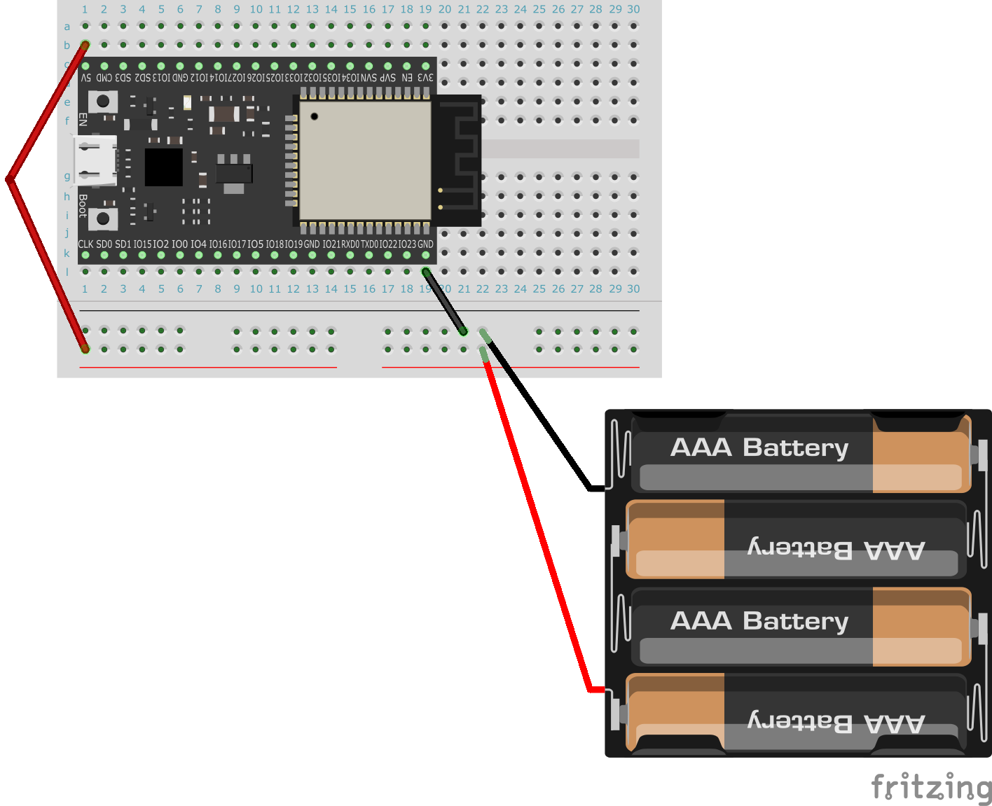
In the table below, "Point A" and "Point B" are directly connected in the circuit.
| Point A | Point B | Notes |
|---|---|---|
| Battery box (+) | Breadboard + rail (right side) | Right rail = 6 V; do not mix with 5 V side |
| Battery box (-) | Breadboard - rail | - |
| ESP32 5 V pin | Breadboard + rail (left side) | Left rail = 5 V; do not mix with 6 V side |
| ESP32 GND | Breadboard - rail | - |
As noted above, the left and right sides of the + rail carry different voltages.
- Mixing 6 V and 5 V on the same rail half will damage the ESP32 and actuators.
Please wire carefully.
Wiring diagram for ESP32-DevKitC:
Operation#
Startup Procedure#
Follow the startup procedure here.
Setup is complete once all programs start and communication is confirmed.
Next#
Next, follow the guide for: