 smabo
smaboRoadmap#
This page is the guide for the 'Base Parts' node on the roadmap below.
This guide assumes you have completed the smabo-app setup.
Overview#
This page explains how to create the base parts.
Specifically, you will:
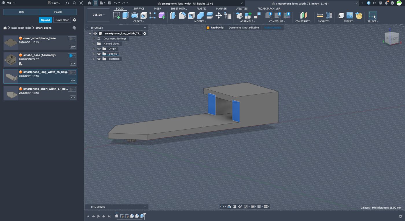
- Modify the 3D model to fit your smartphone
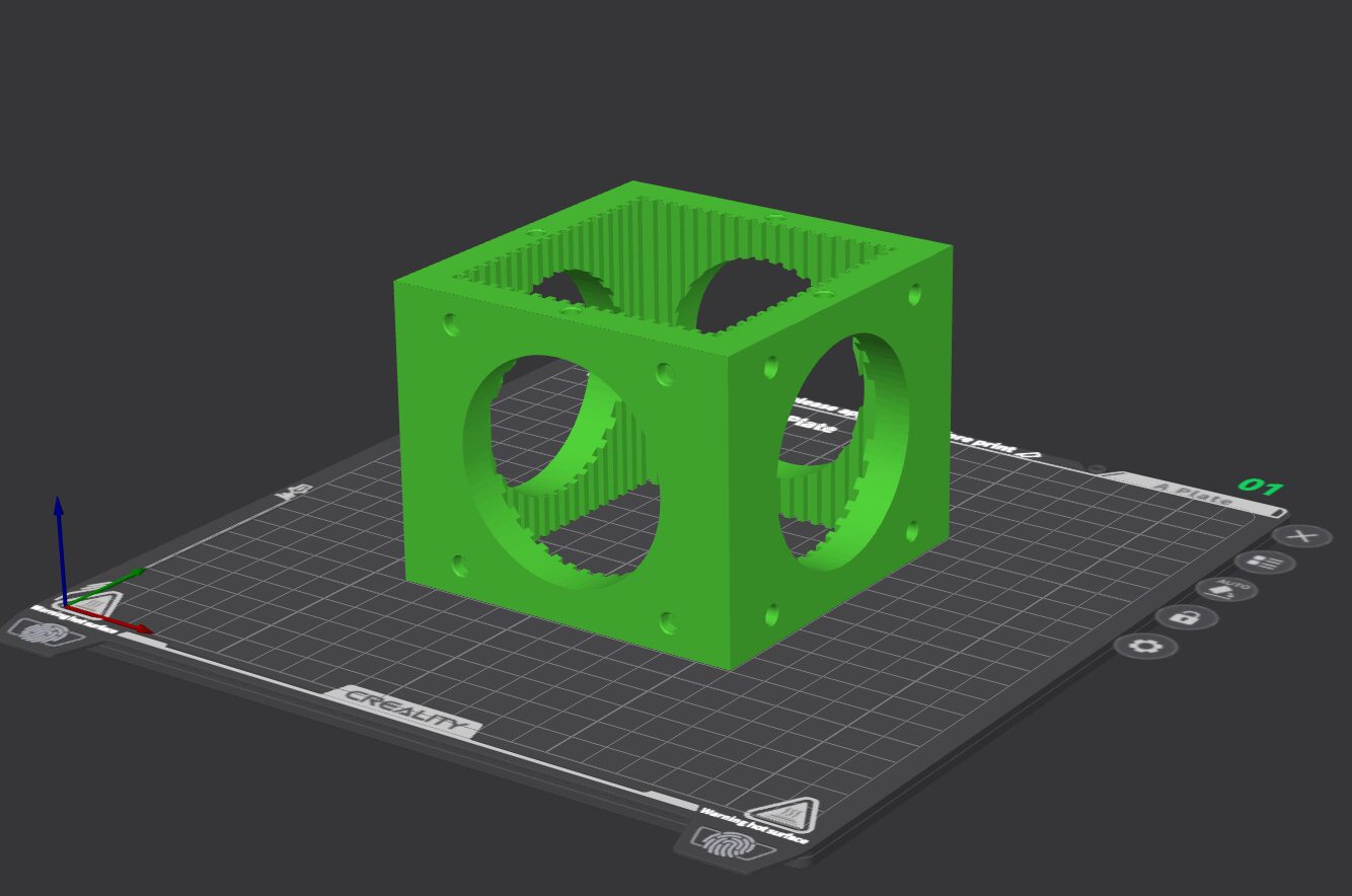
- Print base parts with a 3D printer
Required Parts#
The following parts are required to implement this feature.
| Part | Product URL | Notes |
|---|---|---|
| Smartphone | - | Your own smartphone |
Downloading the smabo-hardware Repository#
First, download the smabo-hardware repository, which contains:
- STL and STEP files for 3D parts used in smabo
https://github.com/smabo-smartphone-robot/smabo-hardware
The smabo-hardware repository contains all parts. Download it to a convenient location — you'll use it throughout the build.
Adjusting Smartphone Mounting Parts#
smabo can hold your smartphone, but phone sizes vary from person to person. This section explains how to adjust the mounting parts to fit your phone.
Measuring Your Smartphone#
First, measure your smartphone's:
- Long side
- Short side
- Thickness (measure the thickest point if the camera protrudes)
Measure in millimeters. If you use a case, measure with the case on.
Caliper
You can check the manufacturer's spec sheet, use a ruler, or — recommended — use a caliper.
A caliper is a precision measuring tool that gives more accurate readings than a ruler. It is commonly used in robot building. If you don't have one, consider purchasing one.
Adjusting Part Dimensions#
Next, follow these steps to resize each part to match your phone.
CAD software
Any CAD software works. Fusion 360 steps are shown as an example in the notes below.
Left/Right Mounting Parts
Import "smabo-hardware/step/smart_phone/smartphone_long_width_75_height_11.step" and adjust so the distance from part tip to inner face equals:
- (phone long side / 2) + 1 mm
Fusion 360 step-by-step
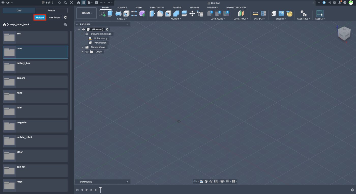
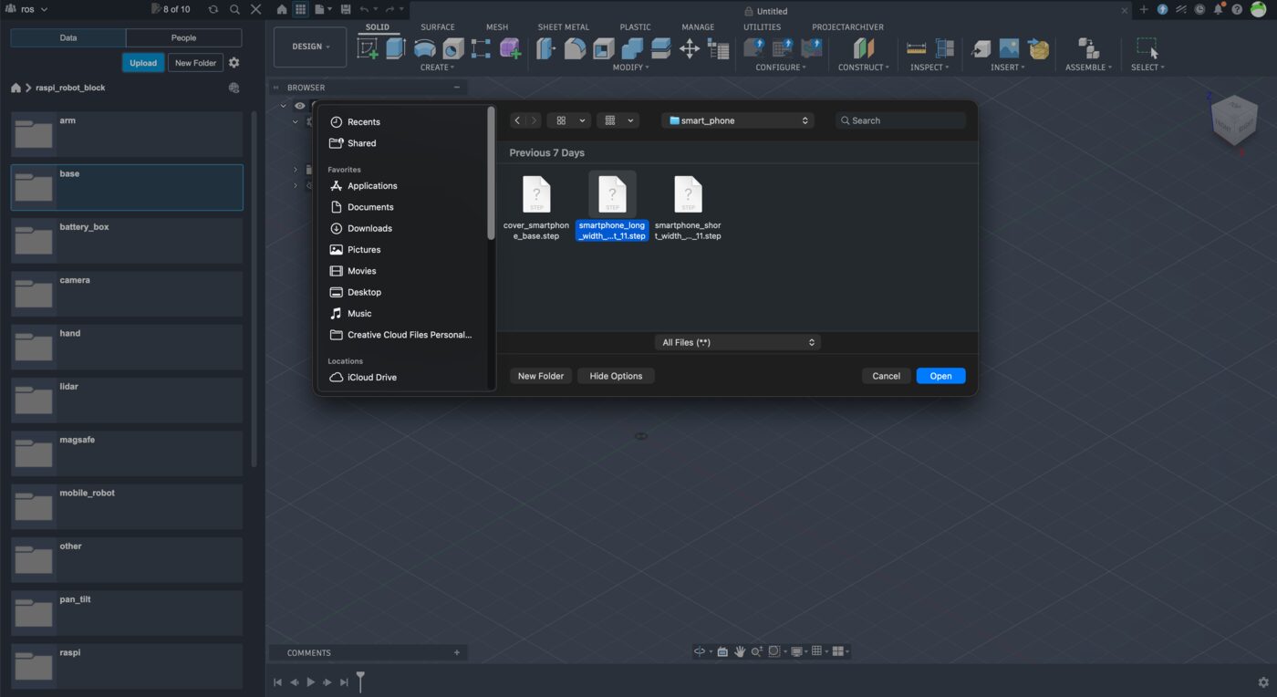
Click "Upload" in the left panel.
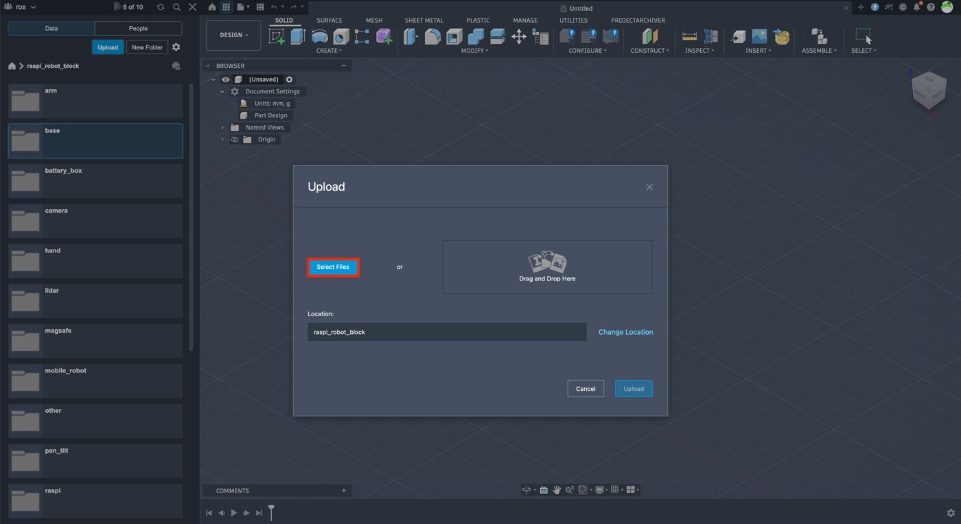
Click "Select Files".
Select "smartphone_long_width_75_height_11.step".
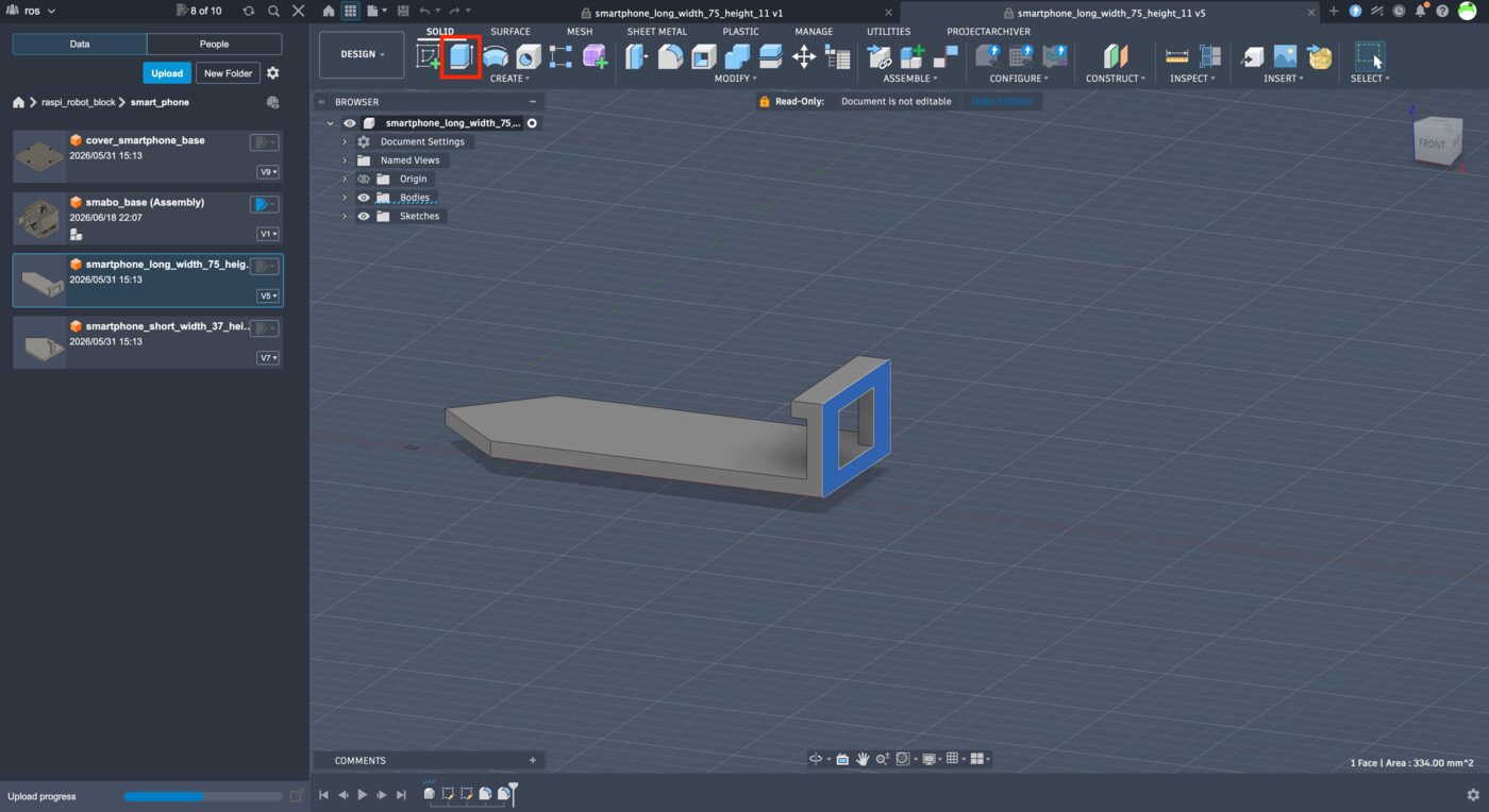
After the import completes, open smartphone_long_width_75_height_11.
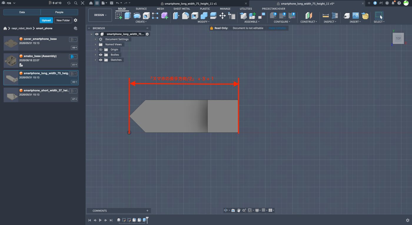
Select the outer face and click "Extrude".
Set the length to (phone long side / 2) + 3 + 1.
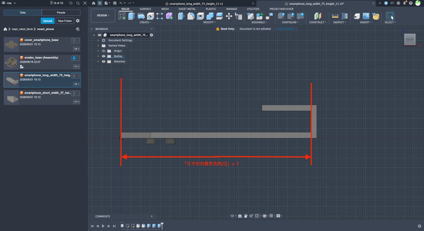
Select the inner face and click "Extrude".
Set the length to (phone long side / 2) + 1.
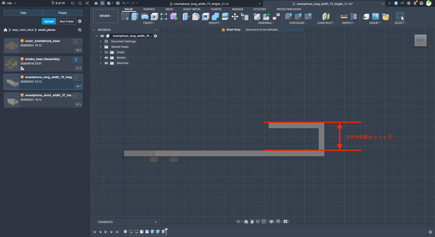
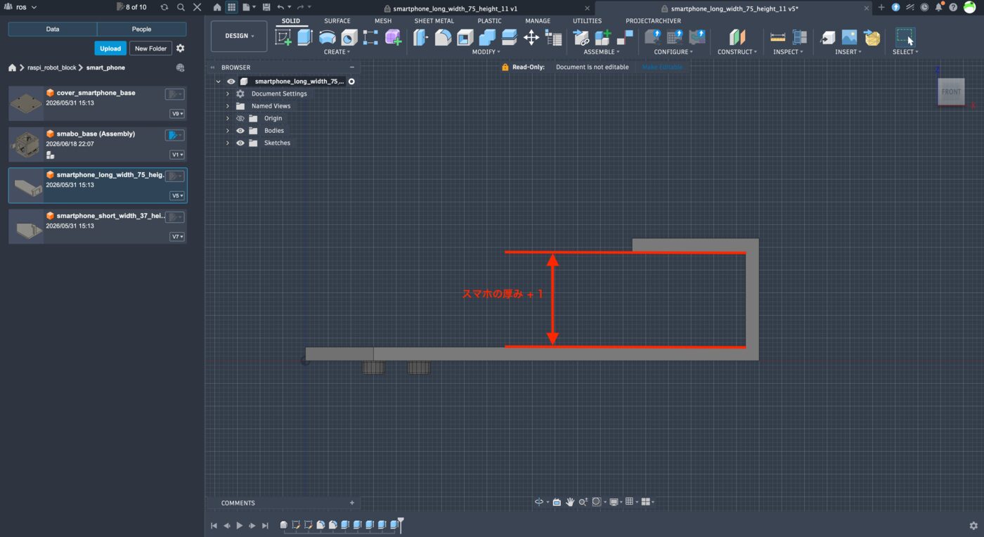
Also adjust the distance from the top to the bottom face of the clamp section to:
- phone thickness + 1 mm
Fusion 360 step-by-step
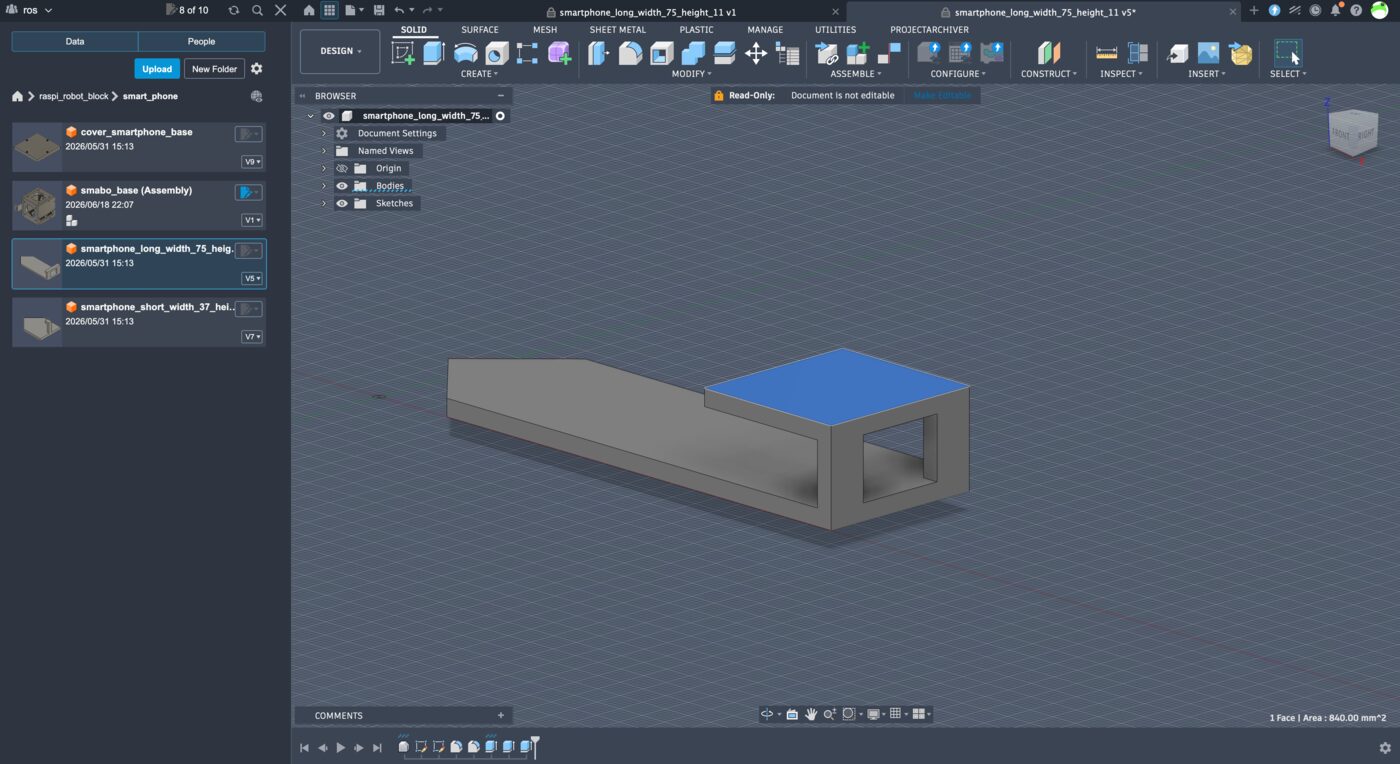
Select the top face and click "Extrude".
Set the length to phone thickness + 1 + 3.
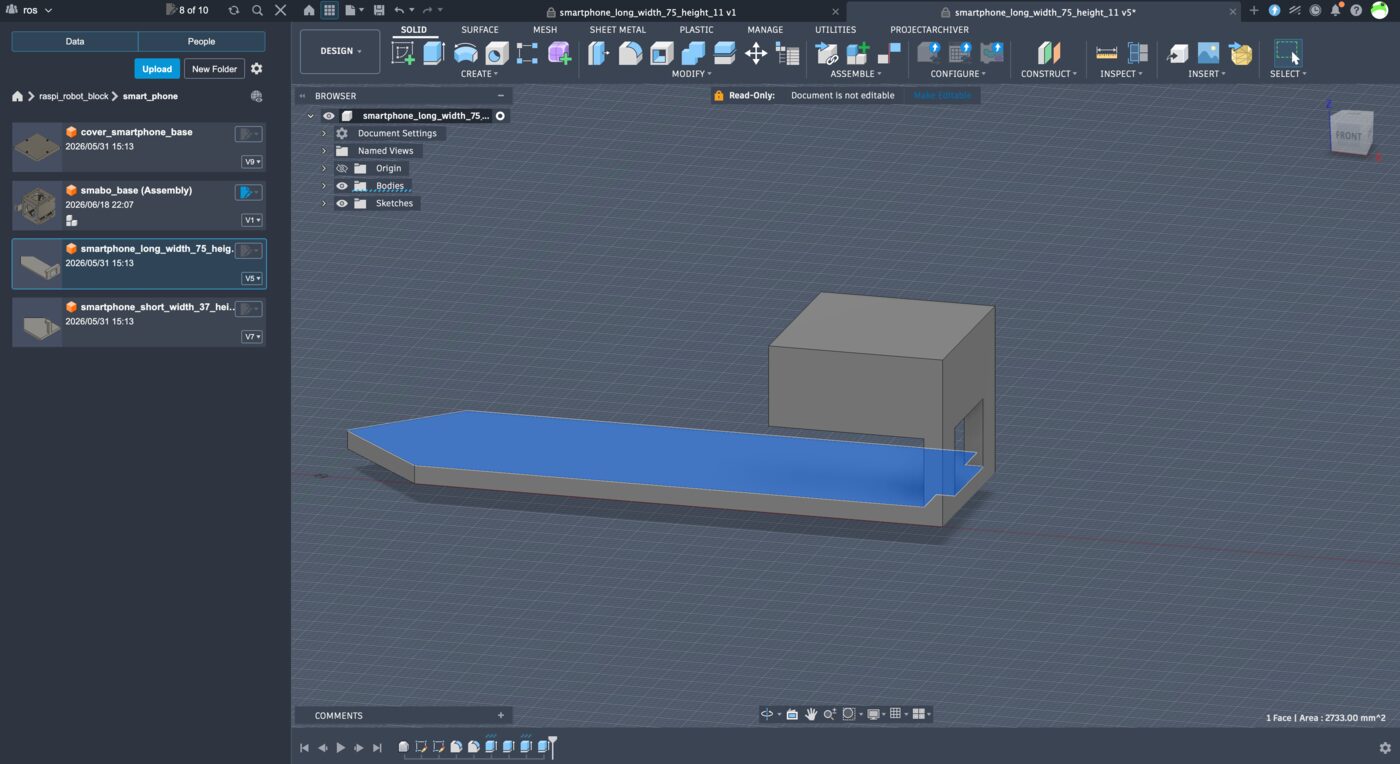
Select the bottom face and click "Extrude".
Set the length to phone thickness + 1.
Top/Bottom Mounting Parts
Import "smabo-hardware/step/smart_phone/smartphone_short_width_37_height_11.step" and adjust so the distance from part tip to inner face equals:
- (phone short side / 2) + 1 mm
Fusion 360 step-by-step
Follow the same steps as for the Left/Right Mounting Parts, using the phone's short side as the reference dimension.
Also adjust the clamp height:
- phone thickness + 1 mm
Fusion 360 step-by-step
Follow the same steps as for the Left/Right Mounting Parts.
Exporting the Parts#
Once you have finished resizing, export the parts as STL files.
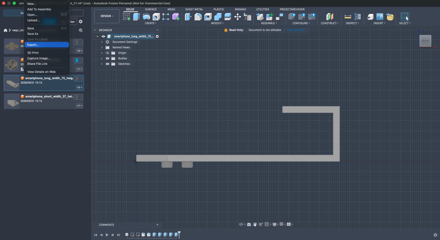
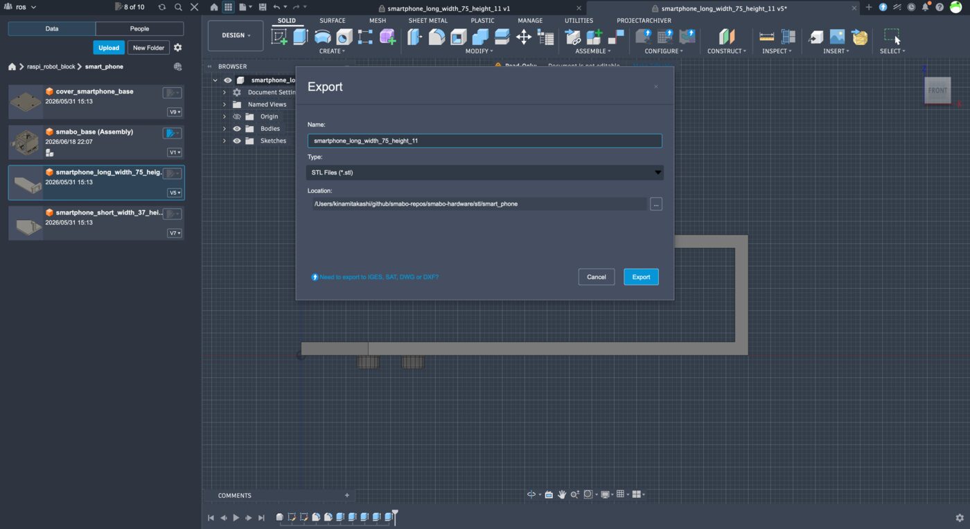
Fusion 360 step-by-step
From the top menu, choose File → Export.
Set the following options and click "Export" to save the file:
- Name: any name you like
- Type: STL
- Location: any folder you like
3D Printing Parts#
Print the newly added parts on your 3D printer.
Because slicer software varies by printer model, only key points are noted here rather than step-by-step slicer instructions.
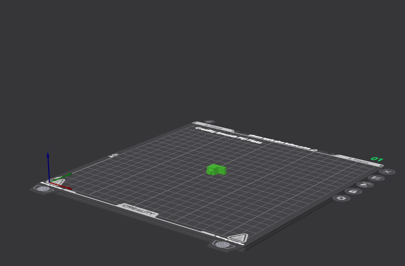
Print the following parts oriented as shown in the images.
Printing tips
- Orient convex protrusions sideways to prevent fractures at the base when attaching/detaching.
- Always enable support material.
Common#
- smabo-hardware/stl/base/base.stl
- smabo-hardware/stl/base/cover_back_bread_board.stl
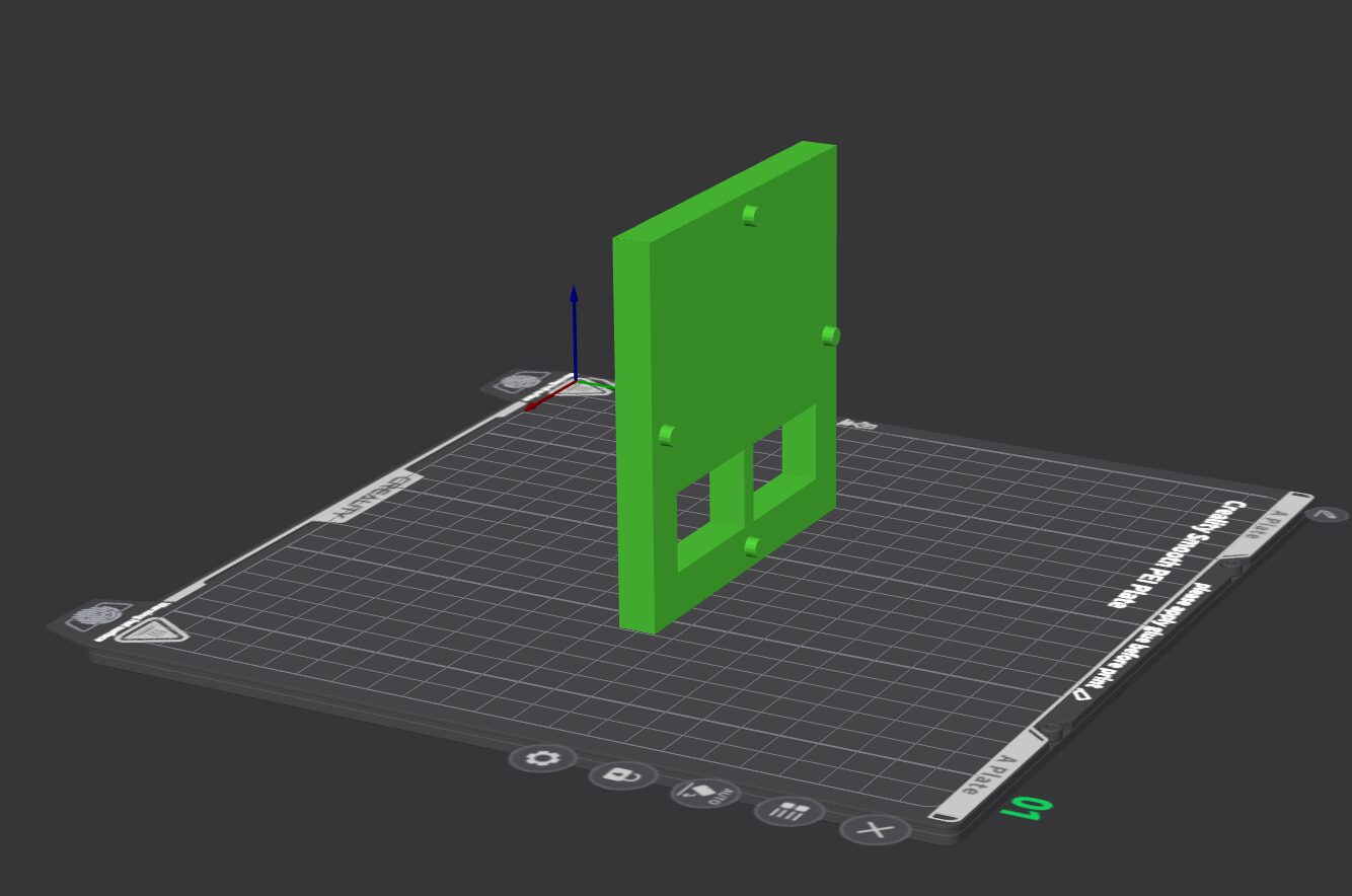
- smabo-hardware/stl/smart_phone/cover_smartphone_base.stl
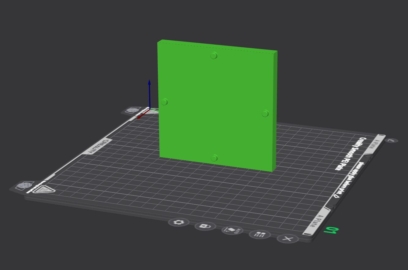
- smabo-hardware/stl/smart_phone/smartphone_long_width_75_height_11.stl (adjusted from original size for your phone) × 2
- Print 2 copies — same part used on the left and right.
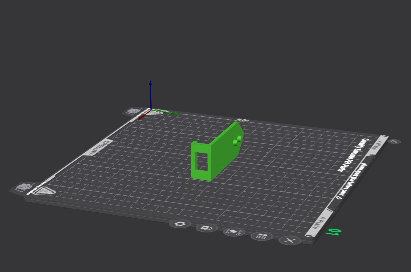
- Print 2 copies — same part used on the left and right.
- smabo-hardware/stl/smart_phone/smartphone_short_width_37_height_11.stl (adjusted from original size for your phone) × 2
- Print 2 copies — same part used on the top and bottom.
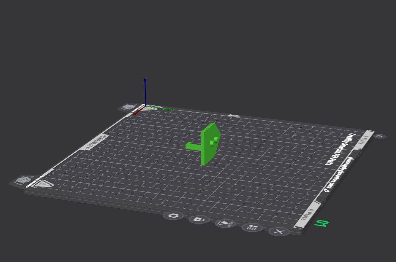
- Print 2 copies — same part used on the top and bottom.
If smabo-brain Is Set Up on an SBC#
For Raspberry Pi (4 or 5)#
- smabo-hardware/stl/raspi/raspi_stand.stl
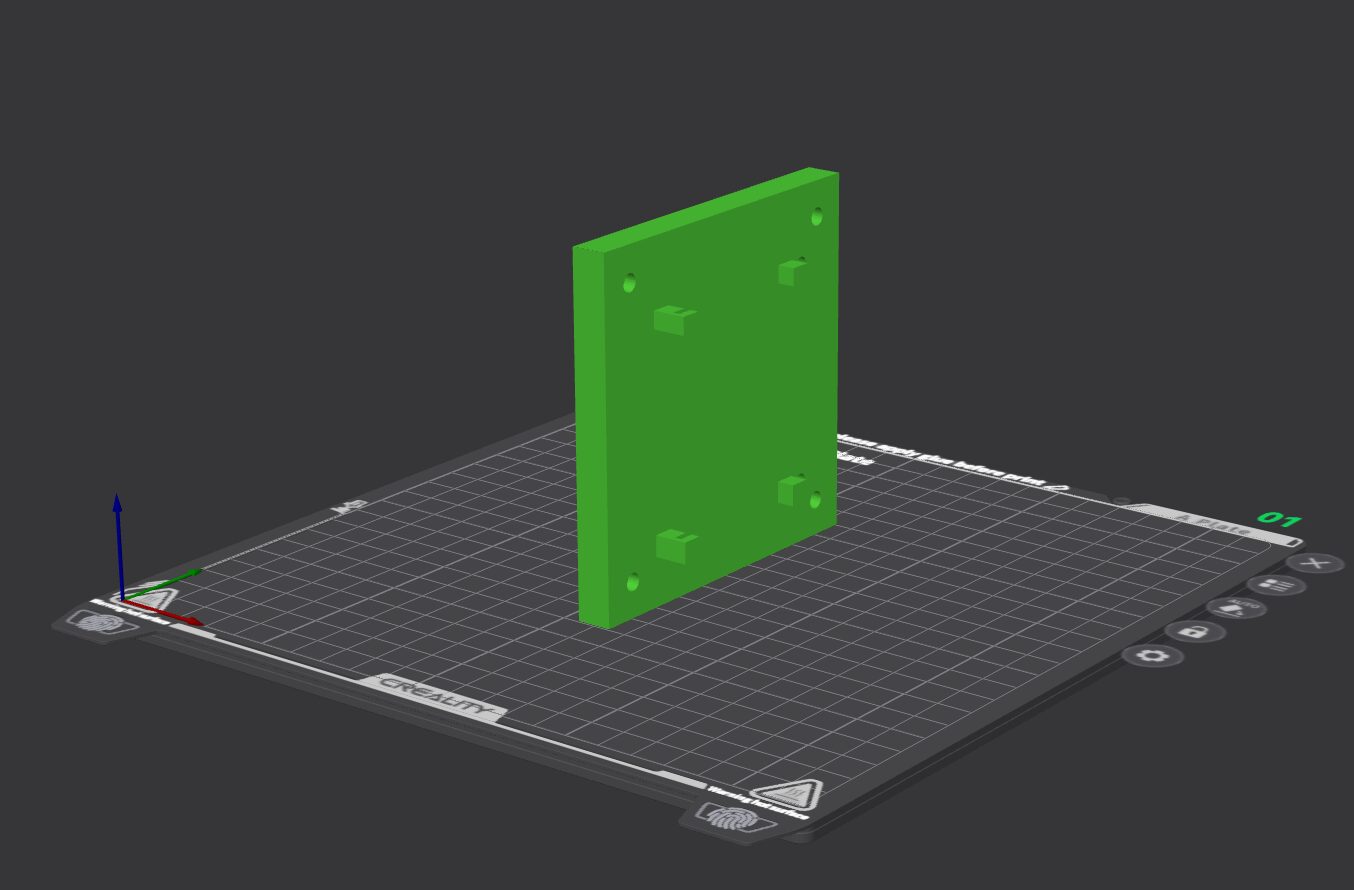
- smabo-hardware/stl/raspi/raspi_stopper1.stl
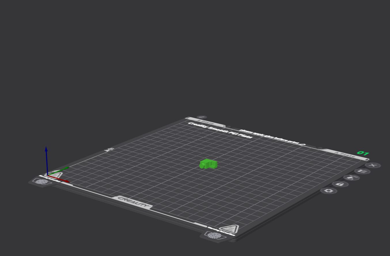
- smabo-hardware/stl/raspi/raspi_stopper2.stl
Assembly#
Assemble the required parts as shown in the video below.
Note: the video also includes parts printed in previous steps.
Common#
Assembly tip
If you plan to remove your phone frequently, you can leave only the bottom part installed and slide the phone in and out from the top. Note that if the robot is inverted the phone will fall out in this configuration.
If smabo-brain Is Set Up on an SBC#
For Raspberry Pi (4 or 5)#
Assembly tip
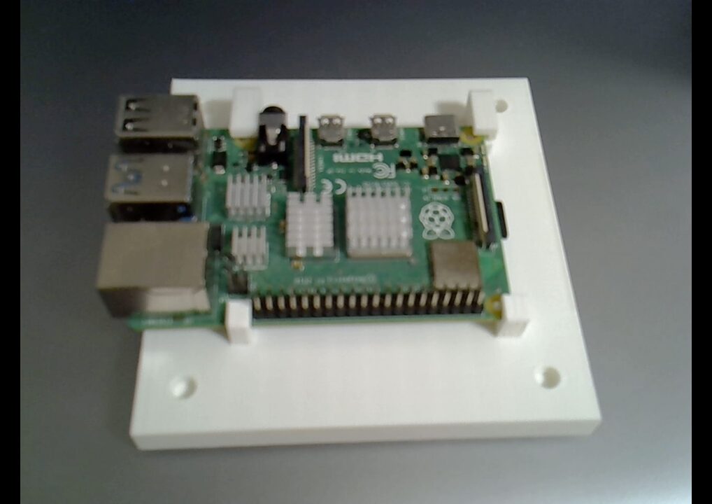
Fix the Raspberry Pi to raspi_stand using the parts shown below.
Attaching Your Smartphone#
Verify that your smartphone fits securely.
Finished Result#
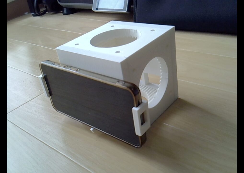
The completed base looks like this:
Next#
Next, follow the guide for: